JESSE SHIRLEY’S BONE AND FLINT MILL
During the late 17th century the beneficial use of ground flint when added to clay to form the body of pottery items and glaze was discovered. Locally, from 1720 flint (silica) was added to clay to produce stoneware type products. It gives the ware strength, and when used with china (white) clay, whiteness, and prevents shrinkage during firing to make a hard cream coloured ware. The problem with ‘grinding’ flint using the technology of the day, which consisted of crushing, pounding and sieving was that it produced clouds of dust. The workers quickly died of “Potters Rot” (silicosis of the lungs) and would not undertake the work. In 1726 a wet grinding method was developed by Thomas Benson to reduce harmful dust. This was adopted by the industry and is used at Shirley’s Bone and Flint Mill.
Shirley’s Bone and Flint Mill

The Use of Flint in the Manufacture of Pottery courtesy of Potteries Heritage Society
The Processing of Flint for the Manufacture of Pottery courtesy of the Potteries Heritage Society
Jesse Shirley’s Bone and Flint Mill in operation following restoration as may be seen today
The 1820s beam engine can be seen driving the grinding pans though the line shaft and bevel gears

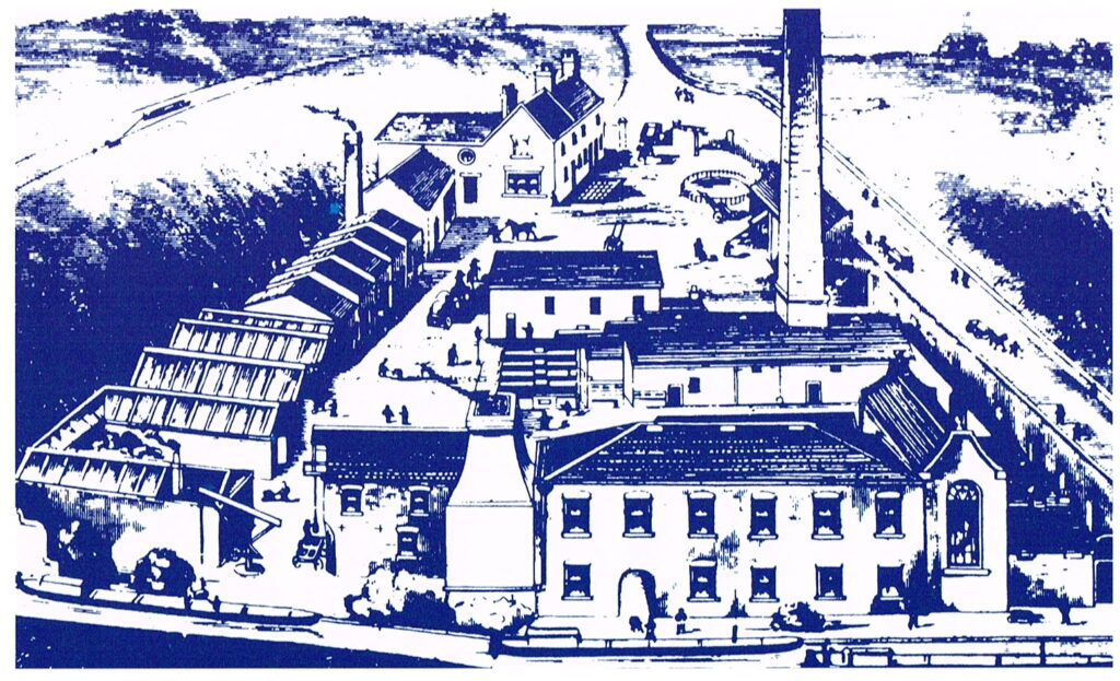
The mill site as constructed by George Kirk for Jesse Shirley, both of Etruria, in 1857. The buildings in the foreground, the machinery contained and the chimney remain largely unaltered.
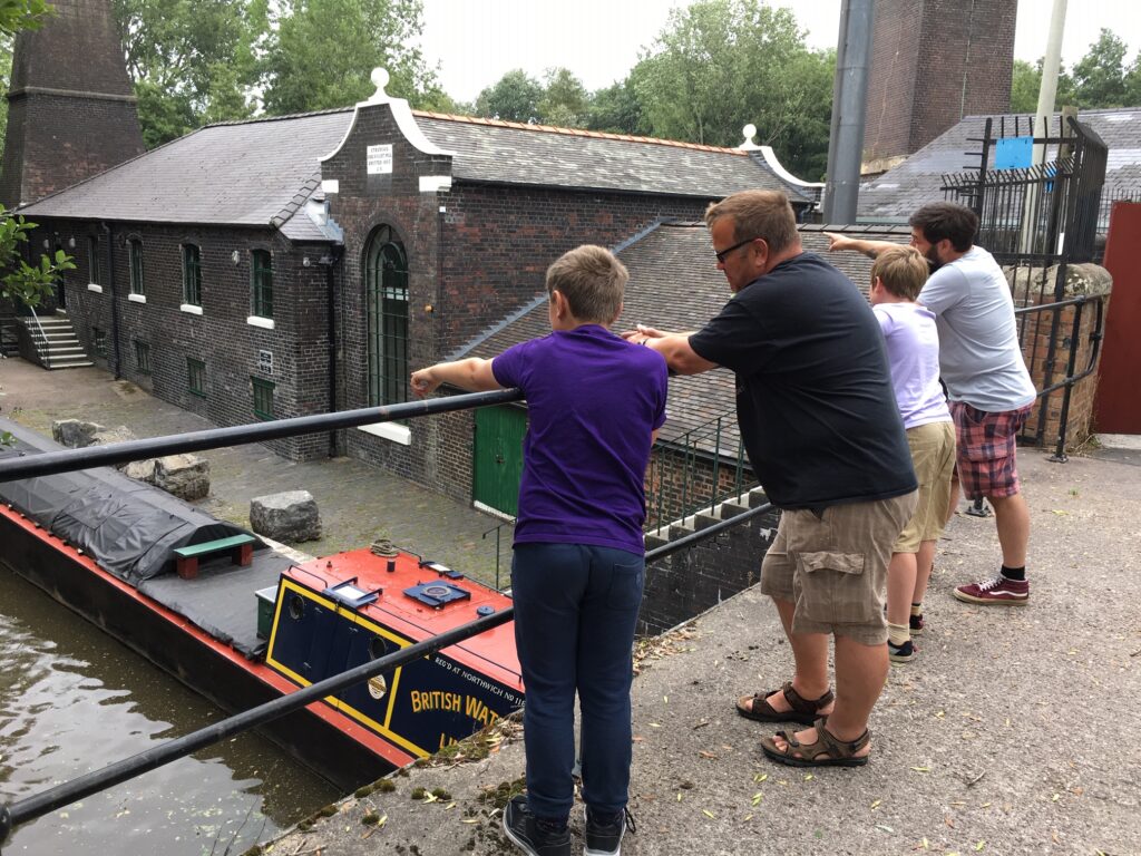
Road access to the site was and is poor but the location was chosen because of the proximity to the canals and the availability of a wharf so providing easy access to many local potteries and to all parts of the country.
Bone, usually from cattle, would originally have been sourced locally but as demand increased it was sourced from various parts of the country and latterly from overseas. Flint was from the south and east coasts of England and near continent.
Calcining Kiln
 The kiln was used to calcine (roast) flints.
In their natural state flints are hard and black. When calcined to above 900 degrees centigrade, crystalline water is driven off to leave a softer, lighter and whiter product suitable for grinding to a fine powder. The calcining kiln consists of two chambers with a hovel built above to create a draught to aid combustion. Firing the kiln was a very skilled job. Flints would be built up in layers with slack (small pieces) coal using approximately 1 hundredweight (51Kg) of coal per 1 ton (1.02 tonnes) of flint. It would be allowed to combust for 8 to 16 hours (depending on the fuel and climatic conditions) and then left to cool before being withdrawn through draw holes at the bottom. Use of the kiln that can be seen ceased in the 1930s but more modern kilns were used.

Bone was treated in a similar way after first being boiled to remove tissue. This would produce glue, a saleable by-product. Wood was used as the fuel as bone is more combustible and is pro
ne to contamination from iron pyrites in coal. Calcined bone is softer and whiter than in its natural state. The bone calcining
kilns have been lost due to past modernisation of the site but were very similar to the flint kiln, probably slightly smaller.
Crusher Room

This is now entered down steps but originally the floor was level with the canal wharf outside. Mining subsidence has lowered the whole area by about 6 feet (2 metres) and the canal wharf has had to be raised to maintain the canal water level – see the blocked up lower part of the windows in the Gear Room. Here are the two draw holes for the kiln.
The crusher was installed in the 1930s after the calcining kiln seen today was decommissioned. It is of the oscillating jaw type, belt driven by a small horizontal steam engine of unknown manufacture and date and was used to crush oversize flints and Cornish stone.
Gear Room

Motion is transmitted via the flywheel axle of the engine through a ratchet which enables the engine to be barred backwards by hand if it has stopped on a dead centre and for maintenance without moving any of the machinery backwards. Rim gears transmit the power to long line shafts which run the length of the room. One shaft is currently driven. Along each line shaft are five bevel gears which transmit the motion to vertical shafts which drive the grinding pans in the room above.
To separate coagulated particles in the ground mix, it was run off from the pans in the upper room through wooden launders to one of three wash tubs, where rotating paddles would stir the mix and ‘blunge’ it through the vertical bars of the paddles.
The suspension, locally known as a slop, was then run into rectangular settling arks. Much larger arks holding 25 tons (25.4 tonnes) of liquid were beyond the gear room wall and have been lost during development of the site. As the solid particles settled wooden bungs in a vertical plank were knocked out to run off the clear water. This left a thickened slop which could be put into barrels and sold or pumped to drying beds (which have been lost) where water was evaporated off and the solid product sold as blocks.
Above the arks is a rare ‘Pulsometer’ steam pump. It has two chambers; steam pressure empties one side whilst the vacuum from condensed steam draws fresh liquid into the other side. A steel ball then rocks over a knife edge to allow the process to be repeated on the other side.
Pan Room
 Material to be ground was hoisted through a hatchway in the floor from the Gear Room below. The slack chain hoist was driven from the extended vertical shaft of the small end pan. The material was tipped into one of ten pans and water added. The pan floor is composed of chert blocks with the gaps filled with ‘pitcher’ (broken biscuit ware). Chert is a siliceous rock, very similar to flint in its chemical composition, and found in Derbyshire, Flintshire and Yorkshire. Power from the floor below rotates sweep arms which push large chert blocks or ‘runners’ around the pan. The material is pushed and tumbled and ground in the process
The larger diameter pans contain runners of up to 1 ton (1.02 tonnes) in weight and a hand crane at one end of the room was used to lift these into the pans. After about 8 hours for flint, less for bone, the material was ground and could be run out of the pan to the floor below for further processing.
Boiler Room

Steam is generated by a ‘Cornish’ boiler built by William Evans at the nearby Cliff Vale Boiler Works in 1903. It is hand fired with coal and contains about 2,500 gallons (11,000 litres) of water, indicated in two water gauge frames with the steam pressure by a Bourdon gauge.
The dead weight safety valve releases pressure at 60 pounds per square inch (4.2 kg force per sq. cm), although the boiler is operated at less than half that pressure. It is important to maintain the water level in the boiler and feed water from a large iron tank in the roof was originally pumped in, against boiler pressure, by two Weir steam pumps. Examples can be seen against the side wall. Today electric pumps are used.
To power the engine steam is taken off from the top of the boiler through a large diameter pipe and taken to the room next door.
Engine Room

“Princess” is a double acting condensing rotative beam engine to the design of James Watt. She was purchased second hand and installed when the mill was built in 1856/7. Her previous history is unknown but she was transported from Eccles near to Manchester and was almost certainly built by Bateman and Sherratt of Salford, Manchester in the 1820s. They were rivals and competitors of Boulton and Watt of Birmingham. James Watt referred to them as the “Manchester pirates” although by 1800 the Watt patents had run out.
Steam enters the single large vertical cylinder through a main steam valve and is directed to one end of the cylinder via valves which are operated by a rocking shaft beneath the floor which is, in turn, operated by an eccentric from the flywheel axle. Exhaust steam is converted to water in a condenser (cooled by water from the canal) located beneath the floor. This creates a vacuum in the condenser which is opened to the other side of the cylinder, thus the pressure difference between steam pressure on one side and vacuum on the other moves a piston within the cylinder. The valves change over and the process is repeated on the other sides of the piston. The two gauges on the wall show the strength of the vacuum and steam pressure.
For the engine to be double acting (pull and push) the beam must have a solid connection to the rod which emerges from the cylinder head through a ‘metallic’ gland packing. The piston rod must travel in a vertical straight line but the end of the overhead beam, which transmits the power, transcribes an arc as it rocks. This would try to pull the rod backwards and forwards which it cannot be allowed to do. James Watt overcame this problem with his great invention – parallel motion; a trapezoidal connection. At the other end of the beam is the sweep arm which connects via a crank to the axle which carries a flywheel of 20 feet (6.1 metres) in diameter and 10 tons (10.16 tonnes) in weight. The flywheel’s momentum carries the engine over top dead centre and bottom dead centre when the piston is at the end of its stroke and is not providing power. The axle extends through the wall into the gear room.
Restoration
In June 1978 Jim Kelly, then the Keeper of Social History at Stoke-on-Trent City Museum, called for volunteers to restore the Mill and machinery.
 It had been in continuous use from 1857 until work stopped when modern machinery on site had been commissioned to replace it in 1972. During that time it had seen little alteration and had become neglected during its latter days but was essentially as it had been built well over a century before. The first working party took place on 22nd October 1978 and voluntary work has continued to the present day, with some of the original volunteers still on the team.
The site’s historical significance was recognised in 1975 with it being designated a Scheduled Monument with the buildings being grade 2* listed. The site was officially opened to the public by Fred Dibnah on 6th April, 1991. It continues to be maintained and operated by volunteers.
